

Are Your Resistance Settings Correct?
Cirris has visited manufacturers who are unsure what values to use when setting up tests. While most times manufacturers understand the settings and get them right, occasionally problems occur when incorrect values are used. Problems can be caused if manufacturers leave the default settings or don’t question values passed down from previous supervisors. In many cases these settings are inappropriate for the device or situation.
One area where incorrect settings can impact test results is resistance. This concept can be difficult to understand, therefore making it hard to know how to adjust the settings when building a test program. This article will help you understand resistance and provide tools to ensure your settings are correct.
What is resistance?
Resistance is everything that inhibits the current (the flow of electrical charge). Think of resistance as obstacles that affect the flow of a river. In the wide, deep parts of the river, the water can flow unrestrained. When the river narrows, becomes shallow, or gets blocked by debris, the water cannot flow as smoothly.
In a cable, material, length, and components are like the depth, width, and debris in a river. They can affect the electrical current in a circuit. If a wire is connected correctly, the test will read low resistance. That means current is flowing through the wire as expected and reaching the required connections. If the tester reads high resistance it means something is impeding the current from reaching its destination.
Each wire naturally has some form of resistance that restricts the current. In order to get an accurate measurement, the tester needs to know what resistance to expect. If these settings are entered incorrectly, the tester may report an error when the problem is simply a resistance level set too low or too high.
What do resistance settings mean?
The value required for a resistance setting creates a limit on what is considered good and what is considered an error. For example, if a wire has a low voltage connection resistance value of 10.0 Ohms, connections below this value will be considered good. Resistance detected above this value will be reported as high resistance or an open error.
Connection resistance is only one type of resistance setting. Cirris testers require different types of resistance settings when creating a test program. The following explanations and diagrams should help you better understand what values to use for each resistance setting.
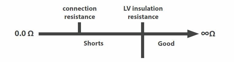
LV Connection Resistance: Checks for intended connections
Resistance detected below the connection resistance value will be seen as connections (shorts if unintended). Resistance detected above the insulation resistance is ignored. Resistance detected between the connection resistance and the insulation resistance will be called a High Resistance Error.

Insulation Resistance: Separates connections, opens, and shorts from what is ignored.
During a Shorts Test, any connection with a resistance measurement above this value is good. Connections below this value are considered shorts.
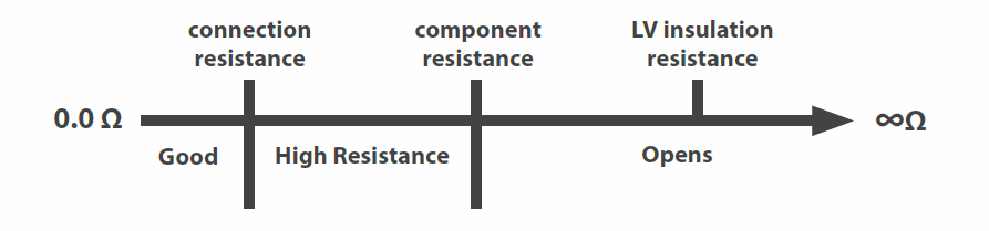
Component Resistance (For Cirris 1100 and Easy-Touch® testers):
This value should be set 5-25% less than the lowest component found in the device being tested.
How component LV settings define errors:
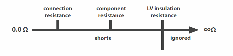
How component LV settings define shorts:
What about High Voltage (hipot)?
High voltage tests usually include an Insulation Resistance test which measures if the resistance of the insulation is high enough. The test checks that no more than an acceptable level of current is escaping the insulation. If the resistance is sufficient, the measured insulation resistance will be equal or greater than the insulation resistance setting for the test.
More about resistance
As mentioned above, all wires have some measure of resistance. The amount of resistance in a wire alone is minimal. If you were to calculate the amount of resistance in a single wire, it would fall below the required setting.
Why worry about resistance when it appears to be such a minor concern? The wire’s own material is not the only thing that causes resistance in a device. Connectors also create resistance. Then the fixturing cables that connect the device to the tester add resistance. All these sources of resistance should be taken into account when setting up a test.
How do you know what value to use?
Cirris has articles and tools that can help.
- Setting Practical Resistance Specs for Continuity Testing
This article discusses how to determine which setting to use for resistance. It is very helpful in knowing where to start if you are unsure what setting to use. - Guidelines for Setting Resistance Test Thresholds
This article also provides advice for determining which values to use for resistance settings. It recommends settings to use for different tests. - Wire Resistance Calculator & Table
This tool can help you calculate the resistance of a wire based on length and gauge. An advanced calculator can help determine resistance for test settings.