With a digital camera and some software tools you can create a large paper image of a harness board. This image becomes a paper template that will simplify documenting, storing, and setting up of any harness board. With the template on your harness board the image can clearly show the placement of the harness and all the fixturing pieces. Templates work well with both the easy-wire grid board approach or with a more traditional (plywood) harness boards. Store the template in your computer and reprint anytime you need it or store a printed copy of the image. This page describes how to create harness board templates for fast and easy setups.
Step 1: Create a blank drawing the size of your harness board.
Use software such as CorelDraw (CorelDraw9 on Ebay for less than $50.00) or Adobe Illustrator to draw a boundary box representing the boundaries of the area you intend to use for your harness.
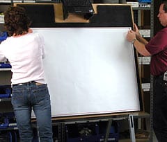
Save this drawing as a “reference” image, then print it. (We recommend using a large-format color printer. If you don’t have a large printer many drafting supply centers or copy centers can make large prints for you.)
Mount this reference drawing directly on your easy-wire grid board, using drawing fasteners. (Cirris part number: EWDF-20)
Step 2: Build up your harness board using easy-wire components.
Mount the easy-wire components directly on top of the reference drawing, poking the pins of the bracket bases through the drawing and into the grid tiles.
Attach your sample wiring harness to the mounted fixturing now attached to the board.
Using a digital camera (3.2 megapixals min.), take a “straight on” shot which fills the whole frame. Be sure the lens is centered over the harness, and that the surface of the harness board and the lens plane are as parallel to each other as possible. (It’s best to move back from the harness board and use a telephoto lens setting to get a flatter field.)
(Tip:) One helpful trick to find the center point with your camera is to put a 3/16″ dowel 16″ long into the center of the harness board (in a tile hole), square up the dowel, then move your camera position until only the very top dot of the dowel appears in the photo. Note : We suggest you limit the image area to 36 inches x 36 inches to avoid distortion at the edges of the field. For larger harnesses, you can “tile” the image using several 36″ x 36″ images.
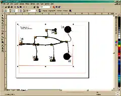
Step 3: Import Image into Software for Clean Up.
Import this digital image/s into your drawing software package. Clean up the image, remove anything on the image that would distract when building a harness. When the images is clean save the new image.
Step 4: Create a 1:1 image
Import your new, cleaned-up image, on a new layer over your original blank drawing (which only has the red boundary box on it) Adjust the image by lining up the boundary boxes on both images. This will create an accurate 1:1 scale image of your harness board setup.
Note: You may have to use commands such as “stretch” or “rotate” to do this.Caution! Be careful not to change the size of the reference boundary box. Place them on their own layer.
Step 5: Add Reference Information to final Harness Board Template.
Add reference designators (J1, J2, J3, etc.), connector specs., part numbers, version info., specialized instructions or any other build information to the drawing, then save the file. Print out the finished template and your ready to go!
To rebuild this test setup in the future, either reprint the drawing you have saved or re-use the plotted drawing you’ve stored. Mount the drawing on your grid board, assemble your easy-wire components as depicted in the drawing, and you are ready to test.